12 Results
View results:
Sort by:
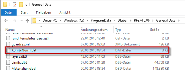
RFEM and RSTAB provide the option to create national annexes with user-defined partial safety factors and combination coefficients. They can also be transferred to other computers.
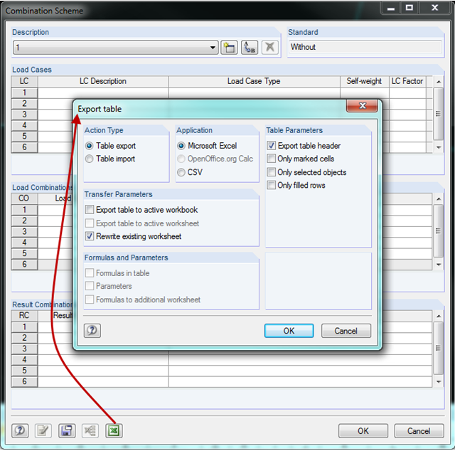
In RFEM and RSTAB, you can create a combination scheme in the combinatorics of load cases and combinations. This scheme can be used for other projects by transferring it to other computers using the Export/Import function. Thus, multiple people working on a project can use the same scheme.
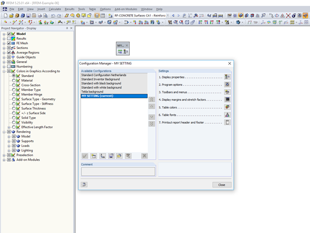
An individual user‑defined workspace can increase your productivity and make your daily work easier. This is why many users take the opportunity to adjust the toolbars in RFEM and RSTAB and to create their own toolbars containing the most frequently used commands.
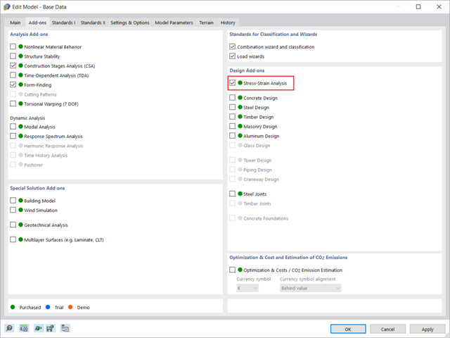
This article shows how to manage the input data for member and surface design configurations within the Stress-Strain Analysis add-on.
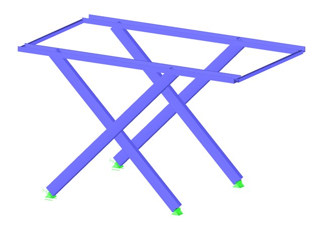
It is necessary to design some structures in different configurations. It may be that an aerial work platform must be analyzed in its position on the ground as well as in the middle and in the extended position. Since such tasks require the creation of several models, which are almost identical, updating all the models with just one mouse click is a considerable relief.
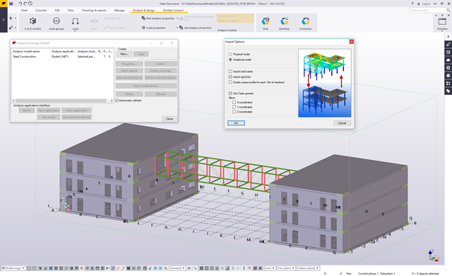
The Master's Thesis of Tamás Drávai, Haroon Khalyar, and Gábor Nagy deals with the effect of interoperability between Computer Aided Design (CAD) and Finite Element Modeling (FEM) software on structural modeling and analysis. Several case studies were conducted, where a building information model was transferred from CAD to FEM software with different data exchange formats.

In RFEM, RSTAB, and SHAPE-THIN, you can create user-defined print templates ("Printout Report Template") and printout headers ("Report Headers"). These templates can also be transferred to other computers and used there.

The RF-STABILITY add-on module determines any critical load factors, effective lengths, and eigenvectors of RFEM models. Stability analyses can be carried out by various eigenvalue methods, the advantages of which depend on the structural system as well as computer configurations.
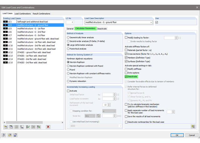
The current state of the development of finite element analysis software and computer technology allows for the calculation of more complex structure. More and more frequently, FE calculations are performed on the entire model. In this context, certain practical construction problems may appear. One of these problems is the consideration of a construction process in the model.
Computer technology has a firm grip on digital structural analysis and design. With each new development, the planners involved are able to increase the limits of what is feasible.

Structures are naturally three-dimensional. However, because it was impossible to perform calculations on three-dimensional models easily in the past, the structures were simplified and broken down into planar subsystems. With the increasing performance of computers and related software, it is often possible to do without these simplifications. Digital trends such as Building Information Modeling (BIM) and new options for creating realistic visualized models reinforce this trend. But do 3D models really offer an advantage, or are we just following a trend? The following text presents some arguments for working in 3D models.
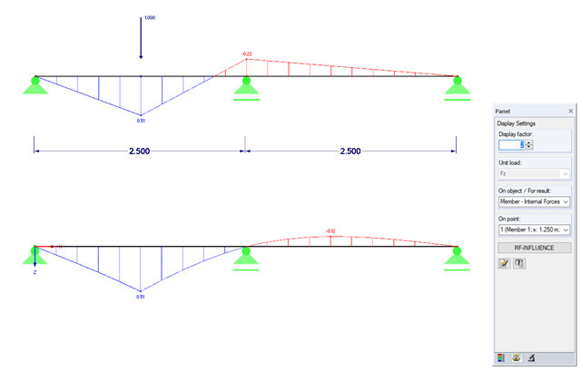
Influence lines are less important nowadays due to fast computer systems. However, it might be an advantage to use influence lines in the phase of preliminary design, as well as in the actual creation of the structural designs. With the RF-INFLUENCE add-on module, influence lines and influence surfaces can be generated and evaluated easily due to a fixed internal force. This technical article describes, with a simple example, the basics of determining and evaluating influence lines.